Microcontrollers

Rotary encoder based cooking timer

Continuing my experimentations with cooking timer user interfaces, I stumbled upon a cute little rotary encoder on Sparkfun. It immediately looked like a good match for the project. The thing is that all cooking timers I’ve seen have either a simplistic interface requiring many clicks to set the time (like clicking the “minutes” button 50 times) or a complex keypad with way too many buttons.

At first I thought I’d need 2 axes (axis 1 would increment by 1 minute and the other axis by 15 minutes) but fiddling around with the trackball showed me that it was not necessary; that I’d just need one axis with tactile feedback (that is, a clicky switch rather than a smooth flowing motion of the controller) and some selection mechanism to switch between 1 and 15 minutes.

The Sparkfun rotary encoder fit the bill – 12 steps for full rotation and clickable! Perfect. I wired up the encoder on the breadboard, wrote the software and then fabricated two one layer PCBs.

The Hardware

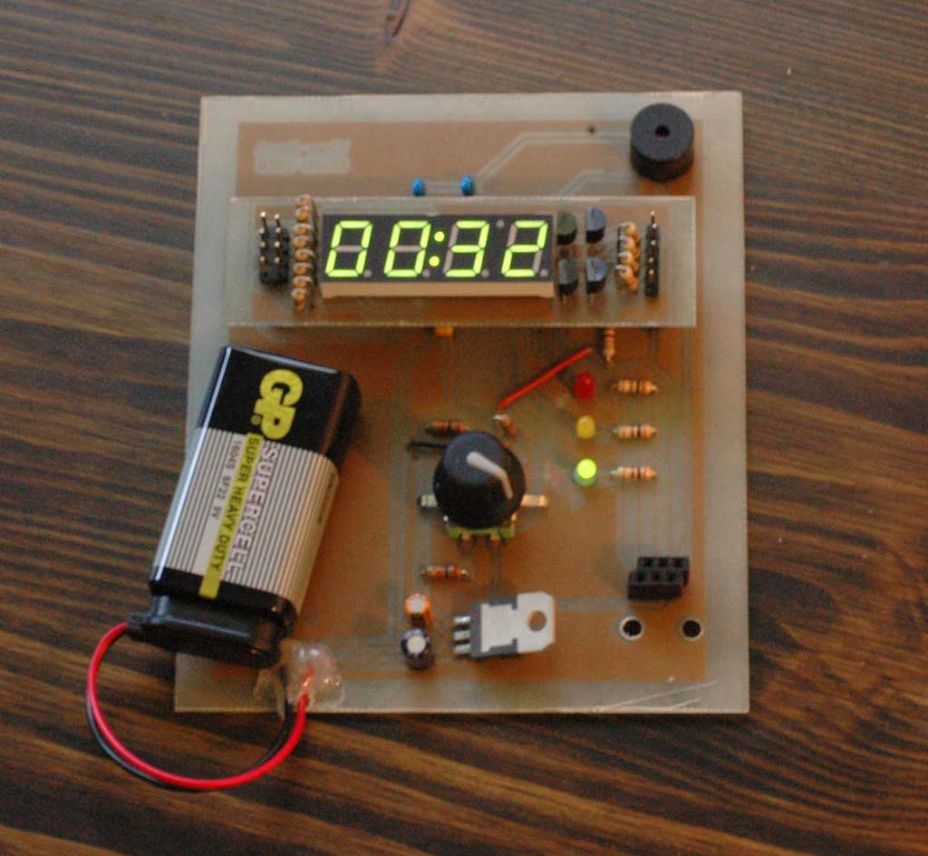
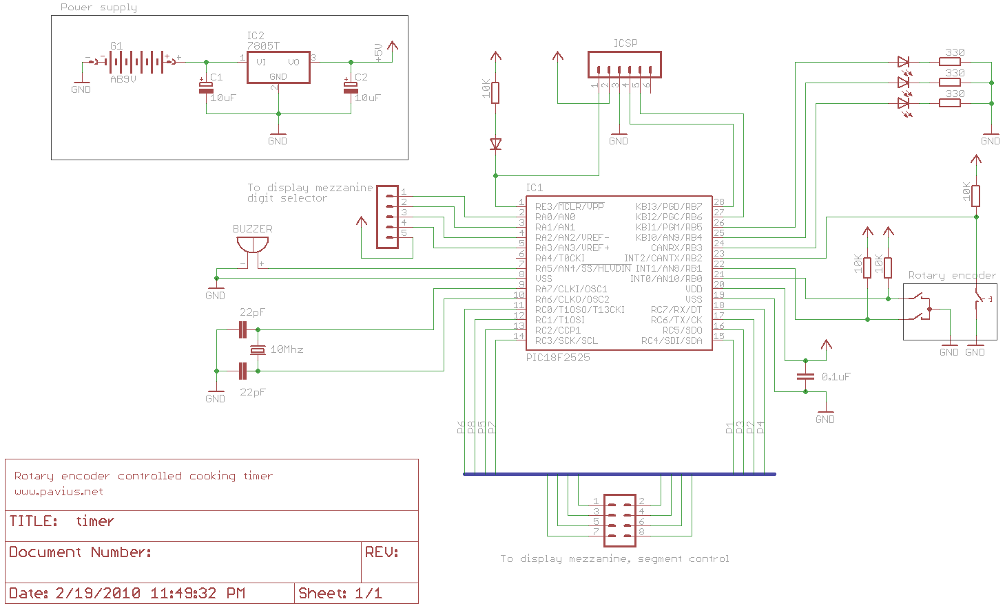
The schematic is fairly straightforward – a PIC18F2525 sits in the middle connected to the rotary encoder (gray code and button), 3 indication LEDs and a buzzer (link to the schematic at the end of the article). The main board connects to the seven segment display mezzanine via two connectors. This board is not, in any way, efficient power wise – it sucks about as much energy as humanly possible.

4 digit Seven segment display

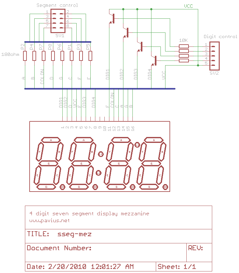
Another Sparkfun gem is the integrated 4 digit seven segment display. The 4 digits are internally connected and there’s even a colon in there – we save a LOT of nets and do not need to flip the 3rd digit to create a colon as there is a dedicated colon segment. The display isn’t huge, measuring in at 4 centimeters across, but will suffice for this test project. Hooking this up to the uC is very standard so I won’t dive into details. The only thing worth noting is that we need to wire up the colon anode to VCC and the cathode to the uC for controlling, holding it at logic high. When we want to light it up we sink the current on the uC by setting the cathode to logic low. You could and should ramp up/PWM this line so as to have consistent brightness with the multiplexed digits (i don’t do it in this project).

Clickable rotary encoder

The rotary encoder from Sparkfun gives two inputs: rotation (CW/CCW) and button click. The rotation interfaces takes the form of a standard gray code output: two channels connected to the uC input pins (w/external or internal pull ups) and ground. The difference between this encoder and the trackball from my previous project is that this is a purely mechanical interface, as opposed to a digital interface with the ALPS trackball. This means that while we received a perfectly filtered gray code signal from the IC on the ALPS, here we receive gray code directly from the mechanical rotation. Each rotation simply connects the channels to ground shifted by a quarter phase. In 99% of the cases we receive a good signal, but those extra 1% bounces need handling. We will see the waveforms in a bit.

The integrated button is as simple as it gets – just like any other button pulled high and shoved into the uC input.

The Software

Rotary encoder state machine

In my previous trackball project I needed to receive an event whenever the trackball moved. This was achieved very easily by simply analyzing the gray code and detecting valid gray code transitions. The difference here is that we don’t want to react whenever a bit change occurs, rather when a complete, valid cycle occurs. This cycle indicates that the user has performed one “click” on the control (there are 12 such clicks in a complete rotation). By detecting such valid cycles we filter out two unwanted events:

  • Mechanical bounces (see rightmost waveform below)
  • The user overshooting and performing an extra “half” click (see middle waveform below)

The software needs to look for two certain valid 4 step flows: a CW click and a CCW click, as shown in the leftmost waveform.

Normally, both channels are pulled up and sit there at logic 1. The CW flow starts by the first channel going to 0 followed by the second channel. The first channel then goes back up to 1 and so does the second. Any deviation of this flow should be filtered out, but mechanical bounces need not cause the motion to be ignored. To fulfill these requirements, I implement this using a two 3 bit “shift register” variables and a simple state machine.

The 3 bit shift registers hold the last 3 polled values of each channel. The polling rate must be fast enough such that 3 polls indicate a stable logic value (you can calculate the polling time required by measuring the shortest bit cycle you can and then diving this by at least 5 – for example if the channel bit is 1ms long when you turn the knob as fast as you can, you should set your polling to at most 200uS). The shift register value is then fed into a pattern matcher – this simply compares the value to either 111 (stable 1) or 000 (stable 0) at any given time. If a match occurs, a bit is appended to the value of the shift register – 0 for channel 0 and 1 for channel 1 (for example, if channel 1 has detected a transition to 0, the new value will be 1000, uniquely identifying an event that channel 1 has transitioned to 0). This new value is then fed into a state machine looking for a 4 consecutive values indicating the 4 step valid flow.

Let’s understand this by looking at how I detect the CW flow above. At first both channels are at 1 so the shift register value is always 111 for both channels. Since we want to detect a stable transition to 0, we set the search pattern for both channels to 000. 3 consecutive polls equal to 0 satisfy the requirements of debouncing mechanical spikes. Once channel 0 goes to 0 for more than 3 polling cycles, the pattern match occurs and the value is fed to the appending mechanism which appends 0 (for channel 0). This value is then fed into the state machine which sees that it indicates the first step of the 4 step flow (channel 0 went down to zero).

The pattern matching for channel 0 is then set to 111 (we want to know when the channel goes back to 1) and the state machine is set to expect the next step: 1000 (channel 1 goes down to 0). In a valid flow channel 1 goes down to zero, the pattern match occurs, 1 is appended to the shift register and the value is fed to the state machine. The search pattern for channel 1 is then changed to 111 and the state machine is set to expect the next step: channel 1 goes back up to 1.

This flow continues until the entire flow occurs correctly. If at any point something is done in the wrong order, the entire state machine and pattern matching resets. This mechanism filters out any “half cycles” performed by the user. Only when the user clicks the rotary to the next notch will the above flow occur. This state machine is written in quadenc.c: quadenc_isr().

Seven segment display

Operating the 4 digit SSD is exactly the same as operating 4 separate seven segments – you select a digit via a transistor, illuminate the desired segments, pause, select next digit and repeat. There are tons of tutorials on seven segments out there so I won’t dive into details. The only thing worth mentioning here is that in my implementation I do two obvious things:

  1. Whenever I want to display a number I modify a RAM array containing 4 bytes – each byte representing a digit and each bit representing the appropriate segment (the position into the byte is the position of the segment in the I/O port). Doing this does not affect the value displayed to the user – it’s all done in RAM – see sseg.c: sseg_setDisplay().
  2. A timer interrupt (shared with the rotary encoder polling mechanism) is set to occur ever X interval (a few milliseconds is fine). When the interrupt is raised I load the next byte (of the 4 bytes modified by the application) into the port. Can’t get any shorter than that. See sseg.c: sseg_isr().

The user interface is a standard state machine driven user interface. The video below has a short walkthrough of the interface. As such, I’ll focus on the button event handling mechanism because this is somewhat reusable over projects.

Just like for every mechanical button, software debouncing is required. This is done by polling the input pin every X ms and shifting this into a 3 bit shift register (no interrupt is used). Once a stable pattern is detected (either 000 for button down, 111 for button up) we can handle this event. However, our timer exports a few cases for the user:

  • Single click: pausing an active timer or switching between 1 and 15 minute intervals
  • Double click: Reseting the timer
  • Long press: Start a timer
  • Press and turn: Select a timer

This requires some code to handle, done in a state machine separate from the user state machine (see ui.c: ui_checkButtonEvent()). The outputted events from this button handling machine are fed into user interface to actually perform the desired event.

Video demonstration and waveform explanation

The following video gives an overview of the timer user interface (interesting unto itself) and then at just over five minutes in shows waveforms for working with the rotary encoder.

Full source can be found on the project Github page. Related Downloads:

Thing UI based on trackballs gestures

I set out to use a trackball to control an alarm clock. It seemed to me like an interesting experiment in UI and another small lesson in electronics. I envisioned using the two axes for controlling hours and minutes (separately and simultaneously) and the tracking speed to specify increments (faster scrolling would mean larger incremcents).

Finding a trackball was not easy. In fact I could only find two – a small clicky trackball from RS (sold also by digikey and mouser – feels pretty crappy) and a beautiful ALPS trackball that was sold by an Aussie company that seemingly unloaded its stock to Roman Black (I got mine directly from him after I mailed him cash). The trackball was surprisingly accurate – no hardware or software filtering was required to receive pure gray code.

After hooking up the trackball I understood that I could not rely directly on its movement to control numeric values with precision as it was too unpredictable. Using a simple “N trackball ticks equal 1 value” did not translate into an acceptable user experience as it proved too difficult to stop at the value we wanted (often going too far and then having to scroll back to correct or conversely, having too great of a dead zone). This would probably work well enough for applications which do not require pin point accuracy like controlling contrast, brightness, movement, etc. However, for setting a precise time this was not good enough.

I decided to decode the trackball gestures instead of numeric value (number of ticks). This would mean defining a set of hand movements against the trackball that would translate into an operation on the clock. To simplify, I decided to control a cooking timer and not an alarm clock as I had already felt at this point that the trackball was not a suitable interface but still wanted to explore detecting gestures. I defined two simple movements – a slow track and a fast track; slow offsetting the timer by one minute and fast by 15. For example, if a user would like to set 50 minutes he would fast track 3 times and then slow track 5 times (on one axis).

Below is an overview of detecting slow/fast tracks with the ALPS trackball. I was able to achieve > 95% success in detecting these two simple gestures (that is less than 1 in 20 movements are detected incorrectly) but found that the trackball is not comfortable enough to operate a timer (currently working on something that hopefully is, details will follow when complete) and decided not to hone this mechanism.

The hardware layer: connecting everything up

The hardware prototype was standard. I used a PIC18F2525 running at 40MHz (10MHz crystal w/PLL – of course you do not need this much horsepower for this task), 4 seven segment displays (multiplexed), a MAX232 for serial and the ALPS trackball. You can read more detail about the ALPS hardware at Roman Black’s excellent page and more about quadrature encoders on google (there are many articles about rotary/quadrature encoders and there’s nothing I can add on this matter). The only worthy thing to report is that I connected the trackball quadrature encoder outputs (2 for each axis) directly to the PIC’s I/O port.

The low level software: Decoding the quadrature encoding

This portion of software needs to perform decoding of the gray code outputted by both axes of the trackball and indicate to the higher layers how many ticks occurred for each axis in each direction. Since, as explained earlier, the gray code is perfect at the PIC’s inputs – there is no special debouncing or filtering required at this stage. There are a few ways of going about this:

  • Polling the inputs in a while() loop: Very simple to implement but should your application be busy doing something like populating an LCD while a change occurred, it might skip an encoder transition and you will receive false counts.
  • Polling the inputs periodically, using a TMR interrupt: By setting up a timer interrupt, you could perform the same polling as using a while() loop, only there would be no chance of missing an encoder transition assuming your application does not mask interrupts for more than a few microseconds. The downside to this is that your application will always spend cycles looking for encoder transitions even when you don’t want it to.
  • Using IO interrupts: Setting up the PIC so that it will generate an interrupt on a change of one of the 4 trackball outputs. I could not do this with the 18F2525 because it did not have 4 free interrupt on change pins.
  • Using a dedicated hardware decoder/counter: For example, LSI offers a hardware quadrature decoder (you would need one for each axis). Some PICs even offer a quadrature decoder peripheral (QEI) – e.g. 18F2331.

I opted for using the TMR polling mechanism as it was the simplest to code and efficient in terms of cost and availability. It is not trivial to guess the polling frequency and there is no “right answer”. On one hand you want to poll as infrequently as possible to preserve cycles but on the other – you might miss transitions and have false reports (you would move the trackball in one direction yet still receive some counts indicating it has moved in the other). I found that there was an extremely small error rate (probably up to the mechanics of my finger slightly moving in the wrong direction as I started to spin the trackball) – at most 2 counts – when I had properly configured the polling rate.

The reason for there being no “right answer” is because this depends on your trackball resolution (256 ticks for one full rotation for the ALPS) and, more importantly, how fast you think the user can spin the trackball (this could be up to the trackball electronics, as well). I found that I could not spin the ALPS faster than about 320uS for one encoder full phase (that is, the bit length of a single encoder output was no less than 320uS). Since the second output will transition in the middle of this bit, we need to poll at least twice in 320uS (or about 160uS). I opted to poll at twice that rate and set up my TMR to 80uS with excellent results. When I used incorrect values (say 250uS) it seemed that for every movement in one direction there is about 10%-30% movement in the other. This happens due to missing transitions and incorrectly reporting the direction as a result.

Once we’ve settled on a way of when to read the quadrature encoder, we need to make sense of the inputs. I’ve adopted Roman Black’s method of comparing bit A of the previous state with bit B of the current state – whether they are equal or not defines the direction. This requires shifting and comparing the inputted bytes but it’s fairly straightforward. The low level software would simply increment or decrement a counter accordingly. This counter was read periodically (using a delay) by the high level portion of the software.

Note: While this project only uses one axis, I thought about how to separate the X and Y axes. It occurred to me that usually a user would only want to operate one axis at a time but would probably fail to move the trackball in only one axis. To solve this “axis bleeding” I devised a theory to check for the ratio between X and Y axis counts during a given high level period. If they were close to 1:1 they would register to both axes, otherwise only the axis with the larger amount of counts would be registered, while the other would register as 0. This would mean that if the user moved the trackball up (intentionally) but also inadvertently to one side, this would be filtered out. However, if the user moved the trackball diagonally – this would indicate that he would like to modify both axes at the same time. Using the count ratio this would be possible – the ratio allowed between X and Y counts would determine the width of allowed diagonal movement.

The high level software: detecting gestures

I wanted to see how exactly a short pulse and fast track looked in terms of counts vs. time to see how I can differentiate between them. I outputted the counts I received to the serial and then plotted a graph. It is very easy to see that slow tracks take longer and contain generally up to 20 counts per high level polling period while the fast tracks are very short with a high amount of ticks per period. I also wanted to have only one event per track – regardless of how long it took. Continuous movement is not feasible with a finger driven trackball.

Using this information a devised a simple state machine.

  • The state machine would sit in Idle state looking at how many counts occurred in the last period. If the counts were 0, this would forever be the case. Once counts are received (indicating that the low level software has detected trackball movement), the values are compared against a threshold – if below, we would move into debounce state; If above, we would move directly into fast track state.
  • When in Debounce state, we wait for the next readout – if it is zero, we would go back to idle and declare no event (thus effectively debouncing small unintentional movements); If it is still not zero but below the high threshold, we would move into slow track state. If it is above, we go into the fast track state.
  • When in Slow track state, we will wait for readouts to occur – if one of them is above the threshold we would move into fast track state. If they are all below the threshold we wait until we receive a zero count (indicating the trackball stopped) and then declare a “slow track” event.
  • Fast track state is very similar – wait until a zero count arrives and then declare “fast track” event.

The state machine is depicted as follows:

The code

You can see the code for this project here. You may also notice that I included a “consecutive medium hits” counter – this accounts for cases that the user performed a fast track that occurred exactly during the polling period. This would cause the large number of counts to be split over two polling periods and not pass the fast track threshold.

Of course, this is a very primitive and non-optimized implementation I prepared over a lazy Saturday. Should your implementation benefit from a finger driven trackball, you may find the ideas in this article useful.

Pictorial: Perfectly flat breadboard jumper wires, every time

As of now, I’ve only been playing around with electronics on and off for a year. The amount of know how in this field is tremendous, but sometimes you find yourself struggling over the simplest of things – for example, cutting breadboard jumper wires to perfect length. After I hastly prototype something on the breadboard (using cheap, flexible, premade jumper wires) and decide to keep it there, the jumper wires I use must be flat and next to perfect. If the wires seem wavy, bumpy or somehow unaesthetic I become homicidal. Below is the method I use to aid my obsession.

I’ll describe the process by preparing a wire to bridge the breadboard power strips.

We’ll start by stripping the tip of the wire as we would normally do, and bending it 90 degrees. Make sure the bare part is not too long (should be approximately as pictured).

We insert the wire into the breadboard, at one of its intended points. We then press our nail firmly on the wire just above the place we want the wire to end. You should make sure the wire is as flat as possible at this point.

We can see that our nail left its mark as intended.

We then take our trusty wire stripper and strip exactly at the grove our nail left. It should be very easy to see and easy to align.

We now bend the second edge of the wire 90 degrees, just as we did to the first edge.

The wire should be the perfect length. Snugly shove it into the breadboard and repeat if necessary.